
Technical Reference
Cleanrooms vs Laminar Flow Benches for Data Recovery
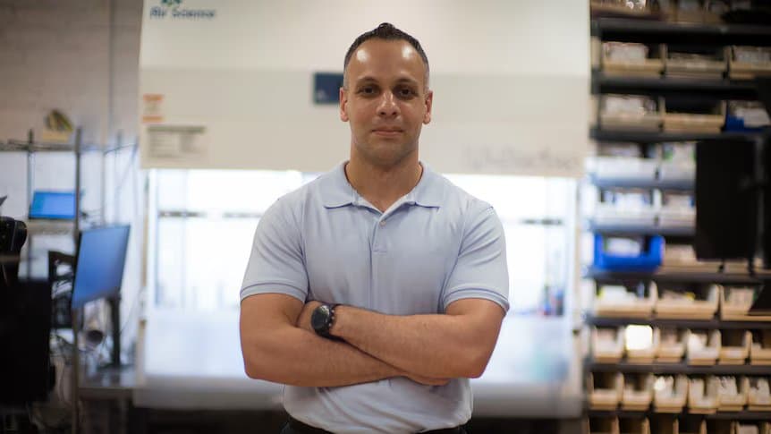
Data recovery marketing frequently references "Class 100 cleanrooms" or "ISO 5 certified cleanrooms" as evidence of technical capability. This conflates two different things: the actual requirement (particle-free air at the work surface during HDD disassembly) and the most expensive way to achieve it (a full cleanroom). Understanding the ISO classification system, filtration technology, and what hard drive data recovery actually requires inside the drive clarifies why clean benches are the appropriate tool and why SSDs never need either.
What Is the ISO 14644-1 Classification System?
ISO 14644-1:2015 defines air cleanliness classes by the maximum number of particles per cubic meter at specified particle sizes. Lower class numbers mean cleaner air. The standard replaced FED-STD-209E in 2001 and uses metric units (particles per cubic meter) rather than the imperial system (particles per cubic foot) of the older standard.
| ISO Class | FED-STD-209E | ≥0.1 µm | ≥0.2 µm | ≥0.3 µm | ≥0.5 µm | ≥1.0 µm | ≥5.0 µm |
|---|---|---|---|---|---|---|---|
| ISO 1 | - | 10 | - | - | - | - | - |
| ISO 2 | - | 100 | 24 | 10 | - | - | - |
| ISO 3 | Class 1 | 1,000 | 237 | 102 | 35 | - | - |
| ISO 4 | Class 10 | 10,000 | 2,370 | 1,020 | 352 | 83 | - |
| ISO 5 | Class 100 | 100,000 | 23,700 | 10,200 | 3,520 | 832 | - |
| ISO 6 | Class 1,000 | 1,000,000 | 237,000 | 102,000 | 35,200 | 8,320 | 293 |
| ISO 7 | Class 10,000 | - | - | - | 352,000 | 83,200 | 2,930 |
| ISO 8 | Class 100,000 | - | - | - | 3,520,000 | 832,000 | 29,300 |
| ISO 9 | Room air | - | - | - | 35,200,000 | 8,320,000 | 293,000 |
All values are maximum permitted particles per cubic meter. A dash indicates the standard does not specify a limit at that particle size for that class. The 2015 revision of ISO 14644-1 removed the ≥5.0 µm limit from ISO 5 because sampling 29 macro-particles per cubic meter was statistically unreliable.
ISO 5 is the classification most data recovery companies reference when advertising "cleanroom" capability. The number "Class 100" comes from the retired FED-STD-209E standard (replaced by ISO 14644-1 in 2001) and refers to 100 particles per cubic foot at 0.5 microns, equivalent to ISO 5's 3,520 particles per cubic meter.
Does ISO 14644-1 Certification Guarantee Clean Air at the Work Surface?
ISO 14644-1 is a room-level certification, not a guarantee of particle-free air at any specific work surface. A certified room meets average particle counts across the entire enclosed facility at audit time. The particle count at the two to three square feet where an open hard drive sits during a head swap is not addressed by room-level certification.
ISO 14644-1 is a room-level administrative certification. Holding it means a third-party auditor has measured the entire enclosed facility against the ISO classification table, confirmed that HVAC, gowning, airlocks, and ceiling fan filter unit (FFU) coverage meet the spec, and reissued the certificate at the documented audit interval. The standard is designed for continuous manufacturing environments such as semiconductor fabs and pharmaceutical fill lines, where every cubic meter of room air must remain controlled for shifts at a time.
ISO 14644-1 audits are conducted in one of three operational states: as-built (empty), at-rest (equipment installed but no personnel), or operational (equipment running, personnel present). The operational state is the most demanding and is the only one that reflects what the air actually does during recovery work.
Hard drive recovery does not need a certified room. It needs particle-free air at the two to three square feet of work surface where the platters are exposed for the 15 to 45 minutes of an open-drive procedure. Those two requirements are not the same engineering problem and they do not have the same cost structure.
We do not hold a facility-level ISO 14644-1 certification. The lab is a working repair shop, not a semiconductor fab. What we do operate is a 0.02 µm ULPA-filtered vertical laminar flow bench. The certification belongs to a room we do not have. What determines whether the recovery succeeds is the air actually touching the platter.
Bench filter integrity is verified by DOP/PAO leak testing as described in the section above. The bench is allowed to run for at least 60 seconds before the drive seal is broken so that the laminar flow field reaches steady state across the work surface.
The drive enters the first-air zone only after the bench has been operating long enough for any disturbed particles from staging activity to be cleared downward through the exhaust.
Airborne Particle Limits and Filter Grades at the Work Surface
Two published standards set the numbers that matter for open-drive work. ISO 14644-1 fixes the airborne particle limits per cubic meter for each class. EN 1822-1 grades filter media by efficiency at the most penetrating particle size, which is the diameter a filter has the hardest time capturing.
ISO 14644-1 Airborne Particle Limits by Class
ISO 14644-1:2015 Table 1 sets the cumulative airborne particle limits per cubic meter of air. The full ISO Class 4 versus Class 5 comparison, reproduced from the standard:
| Particle Size Threshold | ISO Class 4 (particles/m³) | ISO Class 5 (particles/m³) |
|---|---|---|
| ≥0.1 µm | 10,000 | 100,000 |
| ≥0.2 µm | 2,370 | 23,700 |
| ≥0.3 µm | 1,020 | 10,200 |
| ≥0.5 µm | 352 | 3,520 |
| ≥1.0 µm | 83 | 832 |
| ≥5.0 µm | not specified | not specified |
The 2015 revision removed the ≥5.0 µm limit for ISO Class 5 (the older 1999 revision listed 29 particles per cubic meter at that size). Sampling statistics at very low concentrations and particle losses inside sample tubing made classification at the 5.0 µm threshold unreliable, so the standard dropped it for the cleanest classes.
A class number attached to a room says nothing about the two to three square feet of work surface where a platter is exposed. A class number attached to a bench says nothing about the room it sits in. The two are separate measurements of separate volumes of air.
Why 0.02 µm ULPA Filtration Matters at the Slider Air Bearing
Filter physics explains why a 0.02 µm rated ULPA filter is the correct grade for open-drive work even though the filter's Most Penetrating Particle Size sits at a larger diameter. The EN 1822-1:2019 standard (and the global ISO 29463 series derived from it) classifies HEPA and ULPA media by their efficiency at the MPPS, which is the single particle diameter that is hardest for the filter to capture. For mechanical fiberglass media that MPPS typically falls between 0.1 and 0.3 µm. The reason is mechanical:
- Particles larger than about 0.3 µm are caught by inertial impaction and direct interception. They are too massive to follow the airstream around individual fibers and collide with the media on the first pass.
- Particles smaller than about 0.1 µm are caught by Brownian diffusion. Their minimal mass makes them susceptible to random thermal collisions with gas molecules, which causes them to deviate erratically from the streamlines and crash into fibers.
- Particles in the 0.1 to 0.3 µm band are caught least efficiently. They are too small for inertial impaction and too large for diffusion to dominate, so they follow the airstream most faithfully and have the highest probability of slipping through.
The EN 1822-1:2019 grade table makes the efficiency differences concrete:
| EN 1822-1 Class | Filter Type | Integral Efficiency at MPPS | Local Penetration at MPPS |
|---|---|---|---|
| H13 | HEPA | ≥99.95% | ≤0.25% |
| H14 | HEPA | ≥99.995% | ≤0.025% |
| U15 | ULPA | ≥99.9995% | ≤0.0025% |
| U16 | ULPA | ≥99.99995% | ≤0.00025% |
| U17 | ULPA | ≥99.999995% | ≤0.0001% |
A U15 or U16 ULPA filter installed in a vertical laminar flow bench guarantees that even at the filter's weakest size band, the worst-case local penetration is at most 0.0025% (U15) or 0.00025% (U16). For particles at 0.02 µm (20 nm), efficiency is even higher because aggressive Brownian diffusion drives those particles into the filter fibers. The 0.02 µm rating on a ULPA spec sheet is shorthand for that diffusion-dominated capture regime, not a claim that the worst-case MPPS sits at 20 nm.
The reason this efficiency margin matters at the head-disk interface is geometric. The platter-protective DLC overcoat is 2 to 3 nm thick. The PFPE lubricant film is roughly 1 nm. Any solid particle that survives the filter and reaches the platter is, by definition, larger than the gap it has to pass through. The ULPA filter is sized not to match the fly height (no filter can), but to push the residual particle count toward zero across the entire size range that physical contact with a slider would care about.
Documented Slider and Head-Disk Interface Failure Modes from Inadequate Air
If a drive is opened in normal room air, in a degraded cleanroom, or in a bench whose filter has lost integrity, the particles that reach the platter do specific things to the slider, the air-bearing surface, the DLC overcoat, the PFPE lubricant, and the magnetoresistive read sensor. Tribology and failure-analysis literature catalogs the following modes. None of these are abstract risks; each one is described in peer-reviewed studies of recovered slider hardware.
- Particulate embedment in the air-bearing surface. If an external particle is harder than the slider's ceramic composite, the particle can become embedded into the ABS rails. An embedded particle turns the highly polished slider into a secondary cutting tool that machines the platter on every revolution.
- Smear patterns on the air-bearing surface. Hydrocarbons and crystallized siloxane outgassed from drive sealing materials can accumulate inside the air-bearing cavities and near the pole-tip region. The deposits alter the slider's flying stability and shift the local air-bearing pressure profile.
- DLC overcoat scoring. If the air bearing collapses (from contact with a particle acting as a launch ramp, or from shock), the slider strikes the platter at the linear velocity of the disk surface, which exceeds 80 km/h at the outer diameter for a 7,200 RPM drive. The contact strips the 2 to 3 nm DLC overcoat away, exposing the underlying CoCrPt magnetic layer. The signature on the platter is deep, concentric scoring along the contact track.
- PFPE lubricant migration and stiction. The sub-nanometer PFPE lubricant film can migrate off the platter under prolonged thermal cycling or pile up into localized ridges in the presence of contamination. If lubricant pools at the parked head, it can bond the slider to the platter when the drive cools, and the drive does not spin up.
- Thermal-asperity strikes on the read sensor. When the slider strikes an embedded contaminant or a lubricant ridge, friction generates an instantaneous heat pulse. The magnetoresistive read sensor is temperature-sensitive, so the heat pulse produces a large voltage spike in the read channel known as a thermal asperity. Heavy TA strikes overwhelm the drive's error correction codes and produce read failures in regions where the magnetic data is otherwise intact.
Definitive analysis of slider damage requires Scanning Electron Microscopy, often paired with Energy-Dispersive X-ray Spectroscopy to identify elemental composition of embedded contaminants, Atomic Force Microscopy to map nanoscale surface topology, and Auger Electron Spectroscopy to characterize the chemistry of smear deposits. A working recovery lab does not perform that analysis on every drive; it controls the air before the drive is opened so the analysis does not need to be performed. The relevant link back to procedure is the head swap workflow and the chain of custody we describe on the hard drive recovery intake page.
These failure modes are conditional. The text above describes what happens when a drive is opened in inadequate air. None of it describes a specific customer drive, none of it references an internal bench-log statistic, and none of it claims a recovery-rate number. The point is engineering, not anecdote: a U15 or U16 ULPA filter sitting directly above the work surface holds the contamination cascade off the platter for the 15 to 45 minutes the head-stack assembly is exposed during a swap.
What Is Hard Drive Head Fly Height?
Hard drive read/write heads ride on a thin air cushion at a controlled distance called fly height. Modern PMR read/write heads keep a baseline aerodynamic clearance of a few nanometers and use Thermal Fly-height Control to protrude the transducer to an active magnetic spacing of 1 to 2 nanometers. A single 0.5 micron airborne particle is 50 to 100 times taller than this gap, causing a head crash and permanent data destruction on contact.
Inside an operating hard drive, the read/write heads are mounted on ceramic sliders that ride on a thin cushion of air generated by the spinning platters. The bottom surface of each slider, called the Air Bearing Surface (ABS), is precision-etched with rails and channels that create a pressure differential: positive pressure at the trailing edge lifts the head, negative pressure at the leading edge prevents excess altitude. This air bearing keeps the head at a controlled distance from the platter called the fly height.
Modern Conventional Magnetic Recording (CMR) and Shingled Magnetic Recording (SMR) drives maintain a baseline aerodynamic clearance of a few nanometers. Thermal Fly-height Control (TFC) heaters embedded in the slider protrude the read/write transducer further, to an active magnetic spacing of 1 to 2 nm during read/write operations. For scale: a human hair is approximately 70,000 nm in diameter. A strand of DNA is 2.5 nm wide. The fly height is closer to the width of a DNA molecule than to any object visible to the eye.
Above the magnetic recording layer (10-20 nm of CoPtCr alloy), manufacturers deposit a Diamond-Like Carbon (DLC) overcoat measuring 2 to 3 nm thick, topped with approximately 1 nm of perfluoropolyether (PFPE) lubricant. This lubricant reduces friction during incidental contact but is easily displaced by particle impact. Once the DLC overcoat is breached, the magnetic layer underneath is directly exposed and data stored at that location is permanently destroyed.
How Particle Contamination Causes a Head Crash
If a drive is opened in uncontrolled air (ISO 9, typical room conditions with 35,200,000 particles of ≥0.5 µm per cubic meter), particles settle on the platter surface. A single 0.5 µm (500 nm) particle is 50 to 100 times taller than the head fly height. When the slider encounters this particle at platter-edge velocities of 30 to 70 m/s, the following sequence occurs:
- Slider impact. The ceramic slider strikes the particle and bounces off the platter surface, overwhelming the restoring force of the air bearing.
- Lubricant and overcoat removal. The harder ceramic slider scrapes through the 1 nm PFPE lubricant layer and the 2-3 nm DLC overcoat, exposing the magnetic recording layer.
- Magnetic layer ablation. The slider gouges through the 10-20 nm magnetic layer, permanently destroying the data stored at that physical location.
- Debris generation. The ablation produces fine metallic and ceramic debris that is distributed throughout the drive enclosure by the spinning platters.
- Multi-surface cascade. Each new debris particle creates an obstacle taller than the fly height. If a drive has multiple platters and heads, a crash on one surface generates enough debris to trigger secondary crashes across all surfaces.
Once the magnetic coating is scored and converted into airborne debris, the data at those physical locations cannot be recovered by any method. Preventing the initial contaminant from reaching the platter during a head swap is the primary purpose of particle-controlled work environments.
What Is the Difference Between HEPA and ULPA Filtration?
HEPA filters capture 99.97% of particles at 0.3 microns. ULPA filters are graded higher still: EN 1822-1 requires at least 99.9995% capture at the most penetrating particle size for U15, the lowest ULPA grade. Both are sufficient for HDD data recovery. Neither requires a full cleanroom; both are available in bench-top form factors.
- HEPA (High-Efficiency Particulate Air)
- Captures 99.97% of particles at 0.3 microns. The 0.3 µm benchmark sits inside the band where neither interception (effective for larger particles) nor Brownian diffusion (effective for smaller particles) operates at peak efficiency. Used in ISO 5 cleanrooms, hospital operating rooms, and standard clean benches.
- ULPA (Ultra-Low Penetration Air)
- Graded by EN 1822-1 at U15 or higher: at least 99.9995% capture at the most penetrating particle size, which the standard places near 0.12 microns. ULPA filters provide cleaner air than HEPA. A 0.02 micron ULPA filter (the grade used in semiconductor-adjacent applications and in our data recovery clean bench) exceeds what HDD work requires by a wide margin.
The key distinction: HEPA is sufficient for HDD data recovery work. ULPA exceeds the requirement. Both are available in bench-top form factors. Neither requires a full cleanroom infrastructure.
Filter Integrity Testing: DOP and PAO Methodology
Filter performance is verified by challenging the entire filter face, frame, and seals with an aerosol cloud of 0.3 µm particles. Historically, Di-Octyl Phthalate (DOP) was used as the challenge aerosol. Modern testing substitutes Poly-Alpha Olefin (PAO) or Di-Octyl Sebacate (DOS) due to health concerns with DOP. A laser particle counter measures the downstream penetration percentage against the local-penetration limit for the filter's EN 1822-1 grade. These tests are performed during manufacturing, upon installation, and annually thereafter to certify the clean environment.
How Laminar Airflow Creates a Particle-Free Zone
Both cleanrooms and clean benches achieve contamination control through laminar flow: smooth, orderly airflow where air moves in parallel layers without turbulent mixing. The transition between laminar and turbulent flow is predicted by the Reynolds number (Re), a dimensionless ratio of inertial forces to viscous forces in a fluid.
For air flowing through a closed duct, Re below approximately 2,300 indicates laminar flow, with transition to turbulence above 4,000. Open flow over a flat surface remains laminar at much higher Reynolds numbers (up to approximately 500,000) because the boundary layer develops gradually from the leading edge. Clean bench design targets duct-regime Re parameters well below 2,000 to ensure absolute flow stability across the entire work surface, even around obstacles like tools and hands.
Clean benches are calibrated to maintain an air velocity of approximately 90 feet per minute (0.45 m/s). At this velocity, the air has sufficient kinetic energy to overcome the terminal settling velocity of particles ≥5.0 µm, forcing them out of the clean zone before they can land on the work surface. If velocity is too low, heavy particles settle. If velocity is too high, turbulent eddies trap contaminants in boundary layers.
The continuous stream of filtered air creates a physical barrier called an air curtain. Because the bench is positively pressurized relative to the ambient room, the outward flow of clean air prevents infiltration of unfiltered room air. This curtain effect is what allows the work surface to maintain ISO 5 or better particle counts while the rest of the room operates at ISO 9 (ambient) conditions.
Which Laminar Flow Direction Is Best for HDD Head Swaps?
Vertical laminar flow benches are preferred for HDD head swap work because filtered air contacts the exposed platters before passing over any contamination source. Horizontal flow benches push air rear-to-front, across the operator's hands and tools before it reaches the drive. For open-drive procedures, this means vertical flow benches provide cleaner first-air contact at the platter surface.
Clean benches are manufactured in two configurations based on the direction of filtered airflow. The choice of configuration matters for data recovery work.
| Factor | Horizontal Flow | Vertical Flow |
|---|---|---|
| Filter location | Rear wall | Ceiling/canopy |
| Air direction | Rear to front (toward operator) | Top to bottom (downward) |
| First air contact | Air washes over tools and hands before reaching the drive | Cleanest air contacts the drive first; particles are pushed down and away |
| Particle shedding | Particles from operator hands are carried toward the open drive | Particles from operator hands are pushed downward, away from the drive |
| Suitability for head swaps | Suboptimal; contaminant path crosses work piece | Preferred; direct downward filtration onto exposed platters |
Vertical laminar flow (VLF) benches are the standard for head swap operations because the filtered air contacts the exposed platters before passing over any potential contamination source. We use a 0.02 µm ULPA-filtered vertical flow bench for all physical HDD work.
Why a Clean Bench Is Sufficient for Data Recovery
A laminar flow bench provides ISO 5 or better particle counts at the work surface, which is the same spec HDD manufacturers use when assembling drives. A full cleanroom delivers the same work-surface air quality across an entire room.
A full cleanroom is an enclosed room with: positive air pressure (to prevent unfiltered air from entering when doors open), multiple HEPA/ULPA filter units in the ceiling, controlled temperature and humidity, gowning protocols (bunny suits, booties, hairnets), and continuous particle monitoring.
A laminar flow bench is a workstation with a HEPA or ULPA filter that pushes filtered air in a uniform (laminar) direction across the work surface. The air at the work surface inside a properly functioning clean bench meets or exceeds ISO 5 particle counts. The rest of the room does not need to be clean because the laminar airflow creates a curtain of filtered air that pushes contaminants away from the work area.
Data recovery does not need the entire room to be clean. The requirement is specific: when a hard drive is open (the top cover or platters are exposed), the air around the platters and heads must be free of particles larger than the head fly height (a few nm baseline clearance, 1 to 2 nm active magnetic spacing on modern drives). A clean bench satisfies this requirement at the work surface. The rest of the lab can be a normal electronics workshop.
| Factor | Full Cleanroom | Laminar Flow Bench |
|---|---|---|
| Particle target at work surface | ≤3,520 particles ≥0.5 µm/m³ (ISO 5) | ≤3,520 particles ≥0.5 µm/m³ (ISO 5) |
| Filter rating | HEPA (99.97% @ 0.3 µm) or ULPA at ceiling FFUs | 0.02 µm ULPA (EN 1822-1 U15 or better) |
| Airflow pattern | Multi-FFU ceiling-down with return-air mixing across full room volume | Single-pass vertical laminar curtain over a 2-3 sq ft first-air zone |
| Certification basis | Recurring third-party ISO 14644-1 audit (room-level, operational state) | Filter-level DOP/PAO leak test |
| Practical use during head swaps | Drive opened anywhere on a controlled-air work table inside the certified room | Drive opened only inside the first-air zone of the canopy; staging happens outside in ambient air |
| Air quality at work surface | ISO 5 or better | ISO 5 or better |
| Room air quality | Controlled throughout | Ambient (uncontrolled) |
| Gowning required | Yes (bunny suit, booties, hairnet) | No (nitrile gloves only) |
| Airflow duty cycle | Continuous ceiling-FFU recirculation across the room | Continuous single-pass through filter |
| Support space required | Dedicated mechanical plant | None beyond the bench footprint |
| Sufficient for HDD data recovery | Yes (exceeds requirement) | Yes (meets or exceeds requirement) |
Labs that invest in full cleanroom infrastructure carry those capital and operating costs in their overhead. Labs using ULPA laminar flow benches achieve identical or superior localized particle control at the point of exposure during a head swap.
How Does a Poorly Maintained Cleanroom Lose Its Validated Cleanliness?
A certified ISO Class 5 cleanroom can drift far out of specification between recertifications, and the operators inside it usually do not see the drift in real time. Filter loading, pressure-cascade failure, ceiling fan-filter-unit degradation, gowning breakdown, and missed surface decontamination all push the room toward higher particle counts while the framed audit certificate on the wall still claims the room is clean.
The dominant sources of contamination drift inside a cleanroom are well documented in GMP and cleanroom-engineering literature:
- Personnel shedding and gowning failures. A human in normal activity sheds skin flakes, hair, and fiber at a rate of roughly 100,000 particles per minute. Cleanroom gowning (suit, hood, mask, gloves, dedicated footwear) is designed to contain that shedding. If a glove cuff is taped poorly, if a suit zipper develops a leak path, if a face seal slips, or if an operator wears makeup or rubs an eye, the gowning barrier fails and the in-room particle count rises immediately at the source.
- Pressure-cascade failures. A working cleanroom holds a positive pressure differential of 10 to 15 Pascals between the ISO Class 5 core and the adjacent ISO Class 7 gowning ante-room, and a similar differential against ambient. The cascade keeps air flowing outward so unfiltered room air cannot drift in. If a return-air damper sticks, if a supply fan loses head, if a door cycles open too long, or if the building HVAC pulls negative at the wrong moment, the cascade inverts and the core sucks in particle-laden air from the dirtier neighboring spaces.
- Ceiling FFU degradation and filter loading. Ceiling fan-filter units (FFUs) trap particles continuously, which increases pressure drop across the filter face. As pressure drop rises, motor current rises, airflow volume falls, and the laminar field weakens. Individual FFUs can also develop local leaks at the gasket between filter and ceiling grid. Without a periodic DOP or PAO scan and a CPC traverse beneath each FFU, those leaks remain invisible until the next scheduled requalification.
- Surface microbial and particulate accumulation. The vertical surfaces inside a cleanroom (walls, equipment skins, monitor bezels, return-air grills) collect settled particles that re-aerosolize the next time someone bumps the surface, opens a drawer, or pushes a cart past. Without aggressive scheduled wipe-down with validated cleanroom-grade wipers and disinfectants, the room becomes a particle reservoir that releases on disturbance.
- Tool and supply traffic into the core. Every item that enters the cleanroom (donor drives, head combs, torque drivers, anti-static bags, replacement wipers, even the wheel of a transport cart) is a potential particle vector. If pass-through airlocks, decontamination wipes, and material-flow protocols slip, items arrive at the open-drive bench already shedding.
The structural problem is that none of these failure modes triggers a visible alarm. The room continues to run, the badge readers continue to work, the lights remain on, and the framed ISO 14644-1 certificate on the wall is still dated within the audit interval. The operators inside the room observe no change. Only an actual particle measurement performed at the work surface, on the day of the open-drive procedure, would detect the drift.
A vertical laminar flow bench is structurally narrower in scope and therefore narrower in failure surface. The U15 or U16 ULPA filter sits directly above the work area rather than across a 500-square-foot ceiling grid. If the filter has loaded past its acceptable pressure drop, the bench's differential-pressure gauge moves into the red zone and the operator sees the change before opening a drive.
ULPA filtration is not superior to ceiling FFU filtration in absolute terms; the media physics is the same. Properly maintained, an ISO Class 5 cleanroom and a ULPA laminar flow bench both deliver air clean enough for an HDD head swap. The engineering choice for a small lab doing focused open-drive work is the bench, because the failure surface it has to hold clean is a work surface rather than a room.
Why a Vertical Laminar Flow Bench Outperforms a Sealed Cleanroom for Head Swaps
Most commercial cleanrooms are built to ISO 7 or ISO 8 using turbulent air dilution, not unidirectional downflow. A vertical laminar flow bench enforces unidirectional downflow at the only location that matters for a head swap: the two to three square feet directly above the open platter. For a 15 to 45 minute procedure, this solves the correct problem.
A point that cleanroom marketing photography deliberately obscures: most general-purpose commercial cleanrooms are built to ISO 7 or ISO 8, not ISO 5. Per ISO 14644-4, those classes are sealed, positive-pressure rooms that control contamination through non-unidirectional (turbulent) dilution. Filtered air is pumped in through ceiling fan filter units, mixes with the existing room volume, and is gradually pulled out through low-level returns.
The average particle count across the room is controlled, but the airflow inside the room is turbulent. Skin flakes, lint, and wipe fibers shed by a gowned operator do not get pushed straight down and out; they ride the turbulent mixing for some time before the return air pulls them away. That is acceptable for general electronics assembly. It is not the same problem as keeping a single exposed HDD platter free of particles for the 15 to 45 minutes it is open.
A true ISO 5 semiconductor fab does enforce unidirectional downflow at the wafer, but it does so by paying for a full ceiling of filters across an entire room. A vertical laminar flow bench enforces the same unidirectional downflow at the only place that matters for a head swap, which is the chassis itself.
A vertical laminar flow clean bench solves a different and narrower problem. The 0.02 micron ULPA filter sits directly above the work surface. Air leaves the filter face in parallel streamlines moving straight down at roughly 90 feet per minute, encounters the drive, and continues past the chassis to exit through the front opening. The open front is not a contamination risk; it is the exhaust path. The bench is positively pressurized relative to the rest of the lab, so unfiltered room air cannot drift inward against the downflow. Anything an operator brings into the work zone, including hands, head combs, torque drivers, and donor head packaging, sheds particles into a stream that is already moving away from the platter before those particles can settle.
During head-stack assembly removal this geometry matters. The technician's hands come in from the sides of the canopy, below the filter face but above the chassis. Any particulate kicked off a glove or shed by the head comb enters air that is already flowing past the platter on its way out. In an ISO 7 or ISO 8 room running on turbulent dilution, the same shed particle has to wait for the room's air-change cycle to clear it; in the bench, it is gone in a single pass. The room marketing imagery shows the air as static and the room as the protection; the engineering reality is that the air has to be moving in one direction at the work surface, and the bench is the practical way to enforce that during a head swap without paying for an ISO 5 fab around it.
The bench is not a substitute for a semiconductor fab, and it is not trying to be. It is the right shape of clean-air device for a procedure that exposes a single platter pack for a known short window. That is why working data recovery labs around the world, including ours, perform open-drive work inside vertical laminar flow benches rather than inside the kind of room cleanroom marketing photography depicts.
Sterility vs Particulate Control
A common misconception is that data recovery requires a "sterile" environment. Sterility refers to the absence of viable microorganisms (bacteria, viruses, fungi), which matters for pharmaceutical compounding and biological safety. Hard drives are inorganic machines. They do not suffer from biological infection.
The goal of a clean bench in data recovery is strictly particulate contamination control: preventing abiotic dust and debris from acting as mechanical obstructions to the few-nanometer fly height of the slider. The pharmaceutical-grade biological controls found in hospital ISO 5 environments (microbial swabbing, autoclaved tooling, complete head-to-toe sterile gowning) are unnecessary for HDD repair. Bacteria range from 1 to 10 microns in size; the ULPA filter captures them with the same efficiency as any other particle in that range, but the reason is mechanical, not biological.
Why SSD Recovery Never Requires a Cleanroom
SSD recovery does not require a cleanroom or laminar flow bench. SSDs have no moving parts and no read/write heads flying nanometers above a platter surface. SSD work targets the controller chip, NAND flash packages, and PCB using standard electronics bench tools. Particle-free air provides no measurable benefit for any of these operations.
SSDs have no moving parts. There are no read/write heads flying nanometers above a spinning platter. There is no air bearing surface that can be disrupted by a particle. SSD recovery involves working with:
- The controller chip. A surface-mount IC on the PCB. Accessed through SATA/NVMe interface or diagnostic pads.
- NAND flash packages. BGA or TSOP packages soldered to the PCB. If chip-off is needed, they are desoldered with hot air rework equipment.
- The PCB itself. Standard electronics work (soldering, component replacement, signal probing).
None of these operations are sensitive to airborne particles. They are standard electronics bench work performed with soldering stations, hot air rework tools, and diagnostic equipment. A normal electronics workbench is the appropriate environment for SSD recovery.
Cleanroom marketing is about pricing, not particle counts.
Some data recovery companies advertise "ISO 5 certified cleanroom" for all recovery work, including SSDs. An SSD has no component that benefits from particle-free air. Advertising cleanroom capability for SSD recovery is a marketing decision, not a technical one. The relevant question for any recovery lab is whether it has the diagnostic tools (PC-3000, manufacturer-specific firmware access) and the technical knowledge to work with the specific failure mode, not what ISO class its room is certified to.
What Actually Matters for HDD Clean-Air Work
The six factors that determine whether a head swap succeeds in a clean bench are: filter grade, laminar airflow direction, operator discipline, minimized drive exposure time, donor head matching, and helium backfill for sealed-enclosure drives. Filter grade and donor matching carry the most weight; a mismatched donor head can damage the platter as badly as a particle strike.
- Filter grade and maintenance. The filter must be HEPA (0.3 micron, 99.97% capture) at minimum. ULPA is better. Filters must be replaced on schedule; a saturated filter loses effectiveness. Annual DOP/PAO leak testing confirms seal integrity.
- Laminar airflow direction. Vertical flow benches are preferred for head swap work because filtered air contacts the platters before passing over any contamination source. Horizontal benches push air over the operator's hands and tools before reaching the drive.
- Operator discipline. The technician must keep hands and tools within the laminar flow zone. Reaching outside the clean zone and returning over the open drive can introduce particles. Nitrile gloves prevent skin oils and particulates from the hands.
- Minimizing drive exposure time. The drive should be open for the minimum time necessary. A head swap takes 15 to 45 minutes for an experienced technician. The drive is not left sitting open while other tasks are performed.
- Donor head matching. The replacement head stack must match the original drive's firmware version, head count, and physical compatibility. A mismatched donor head can produce read errors that damage the platter surface as severely as a particle strike. Proper donor matching is at least as important as the air environment.
- Helium drive considerations. Helium-filled drives (helium drive recovery) require head swaps to be performed with helium backfill because the head fly height is calibrated for helium's lower viscosity. We perform helium head swaps in-house at our Austin lab, including helium refill. The sealed chamber must be resealed and backfilled after the swap; this adds complexity but does not change the clean bench particle control requirements.
Work-Surface Protocol During an Open-Drive Procedure
Filter grade and airflow velocity set the ceiling for achievable cleanliness. The floor is set by what the technician does inside the laminar zone. Particle counts measured in an empty bench are not representative of counts measured during an active head stack assembly swap; hand motion, tool introduction, and drive orientation all perturb the flow field. The following protocol governs how open-drive work is staged inside the vertical flow canopy at our bench during hard drive data recovery procedures.
First-Air Principle
Filtered air is cleanest the moment it exits the ULPA filter face and becomes progressively more contaminated as it encounters every surface below. The open drive must be positioned so that the air contacting the exposed platters has not first passed over hands, tools, donor stacks, lint from wipes, or the drive's own PCB. In a vertical laminar flow bench, this means the drive is placed near the top of the work zone relative to other items, never downstream of them.
Tool Staging Zones
The bench surface is mentally divided into three zones along the airflow axis. The first-air zone directly under the canopy holds only the open drive and the donor head stack during the swap. The secondary zone holds the torque driver, head comb, and drive cover. The peripheral zone at the bench edge holds closed donor drives, cleaning wipes in sealed pouches, and any item that has not been wiped down with isopropyl alcohol before introduction. Items never cross from peripheral to first-air without an intermediate wipe-down. Tools that leave the bench do not return to the first-air zone without being re-staged through the wipe-down step.
Drive Orientation Under the Canopy
The drive is oriented so that the open platter side faces the incoming filtered air column with the PCB and drive chassis positioned below the platter plane. For a vertical flow bench, this places the platters horizontal and the spindle axis parallel to the airflow, which maximizes the dwell time of clean air over the exposed surfaces before it reaches the chassis and exits the zone. The drive is not tilted during the head-park or ramp-unload step, because tilting introduces a lateral component that pulls air from the peripheral zone across the platter.
Bench-Edge Boundary
Laminar flow holds its parallel streamlines until it encounters an obstacle large enough to shed a turbulent wake or until the jet exits the bench and mixes with room air. Near the front edge of the bench, the boundary between filtered and ambient air is unstable; small pressure fluctuations from operator movement or HVAC cycling can pull ISO 9 room air several centimeters into the work zone. The open drive is kept at least 15 to 20 cm inside the front edge of the bench for the duration of the procedure. Reaching into the work zone is done with slow, deliberate motion; quick hand withdrawal creates a low-pressure wake that drags peripheral air across the platter.
Glove and Hand Discipline
Nitrile gloves are pre-wiped with isopropyl alcohol before each open-drive step to remove residual mold-release particulates from manufacturing. Hands approach the drive from the sides, never passing directly above the open platter. Once gloved hands leave the first-air zone, they are wiped again before re-entry. The technician does not speak over the open drive; respiratory droplets are in the 5 to 20 micron range and will settle on the platter within the fly-height envelope.
Exposure Time Budget
Every minute a drive is open increases the integrated particle exposure, even inside ISO 3-4 equivalent air. The head swap is rehearsed on the donor first: alignment of the head comb, torque sequence of the pivot screw, and cable routing are practiced on the matched donor chassis before the recipient drive is ever opened. When the recipient drive is opened, the entire swap is completed in one continuous operation. The drive is not left open for phone calls, breaks, or secondary tasks. If an interruption is unavoidable, the drive cover is reseated temporarily and the procedure restarts with a fresh first-air stage.
Equipment Operating At and Around the Clean Bench
The clean bench provides particle-free air during the open-drive window. The data extraction itself requires PC-3000 Portable III for firmware diagnosis and head map editing, PC-3000 Express for adaptive-parameter recalibration after a donor head swap, DeepSpar Disk Imager for sector-level imaging, and FLIR thermal cameras for PCB diagnostics before the drive is opened.
A clean bench by itself does not recover data. The bench provides the air environment for the few minutes the drive is open; the actual extraction depends on diagnostic and imaging hardware that lives next to the bench and gets used before, during, and after the open-drive procedure. The following equipment operates at our clean bench during HDD work.
- PC-3000 Portable III
- ACE Lab's standalone hardware-software complex used for firmware diagnosis and Service Area work without a desktop workstation. Connects to the drive over SATA and the manufacturer's diagnostic ports, sends Vendor Specific Commands that bypass standard ATA, and reads, rewrites, or patches translator modules, defect lists (P-List, G-List), and SMART logs. The Portable III is what we use at the bench when a drive needs head map editing in RAM (disabling a degraded head before imaging) immediately before or after a head swap.
- PC-3000 Express
- The PCIe-card variant of the same complex, installed in a dedicated workstation adjacent to the bench. Used for adaptive-parameter recalibration after a donor head swap: the donor heads have slightly different equalization targets, FIR filter taps, and signal-to-noise ratios than the originals, and the SA must be retuned before the read channel will produce stable bit recovery. Express is also the platform we use for ROM extraction and translator rebuild on drives that pass through the bench.
- DeepSpar Disk Imager
- A dedicated imager that sits between the drive and the host at the SATA PHY layer and bypasses the operating system's storage drivers entirely. DeepSpar enforces millisecond-scale read timeouts (rather than the multi-second OS defaults that let a failing head sit over a damaged track), issues COMRESET at the PHY layer when the drive's firmware hangs, and can cycle drive power without OS involvement. It runs the multi-pass per-head imaging sequence we use after a head swap: confirmed-healthy heads at full speed first, marginal heads at reduced retry counts in subsequent passes with mandated cooling intervals between them.
- FLIR Thermal Camera
- Used for non-destructive PCB diagnostics before the drive enters the bench. When a power-event drive arrives, a low current-limited voltage is injected into the suspect rail and the FLIR camera identifies which component is dissipating that current as heat: typically a shorted Transient Voltage Suppression (TVS) diode, tantalum capacitor, or motor controller IC will exceed 80°C within seconds. If the failure is isolated to the PCB the drive never has to be opened. If the FLIR and electrical profiling indicate a dead preamp ASIC on the head stack, the drive is staged for a full mechanical head swap inside the ULPA bench.
The diagnostic equipment is not a substitute for clean air during the open-drive window, and the clean bench is not a substitute for firmware and imaging tooling. Both are required, in sequence, and the bench's only job is to keep the air free of particles for the 15 to 45 minutes the drive's seal is broken so that the subsequent imaging work has a recoverable surface to read from.
Co-Located Bench, PC-3000 Portable III, and DeepSpar: Why Mechanical and Imaging Work Do Not Get Split
A pattern that shows up in the broker side of the data recovery market: a customer drops a drive at a local storefront, the storefront ships it to a partner facility for the mechanical head swap, the patched drive is then shipped to a different facility for imaging, and the imaged data is shipped to a fourth location for delivery. The marketing language describes this as a network of specialized labs. The engineering reality is that every transition adds time on a drive that has just been put into its least stable mechanical state of its entire life.
A drive that has just had its head stack swapped is not equivalent to a healthy drive with a different serial number. The donor read/write heads sit slightly differently in the air bearing than the originals; their preamp ASIC has different bias and gain characteristics; the servo bursts they read off the platter do not produce identical position-error signals. The drive's factory adaptive parameters were written for the original head stack. Until those adaptives are updated in the Service Area against the donor heads, the read channel is operating outside its tuned range. PC-3000 Portable III is the tool we use to push that adaptive update directly to the SA and to install an in-RAM head map that locks out the surfaces we already know are damaged, so that the imaging pass does not waste energy reading sectors that the head crash already destroyed. That work happens with the drive sitting next to the bench, within minutes of the lid going back on.
DeepSpar Disk Imager picks up where the SA work ends. The first imaging pass after a head swap is the most informative pass the drive will ever see, because the donor heads are at their best moment and the heat budget of the preamp has not yet been spent. The DeepSpar policy we run is conservative on the first pass: confirmed-healthy heads at full speed, marginal heads at reduced retry counts, with cooling intervals between heads so that thermal expansion of the slider does not change fly height across the pass. A drive that has to wait for shipping between the bench and the imager loses that first pass. When the drive arrives at the secondary facility, the donor heads have already cooled, warmed, vibrated through transit, and in some cases re-contacted the platter during a shipping shock. The first imaging pass is no longer a first pass; it is whatever the drive can still do after a multi-day non-operating event.
The split-facility model also breaks down for specific failure modes where the time window between mechanical work and imaging is the recovery. Stiction releases are the clearest example: once the heads are unstuck from the platter and parked, the lubricant layer at the contact site is already heavily degraded. The mechanical state is unstable, and the drive needs to be spun up and imaged immediately. Subjecting a stiction-recovered drive to shipping shock and vibration before imaging increases the risk of a repeat head-to-platter event before any data is read.
Preamp ASIC failures carry their own transit risks: the donor preamp and donor head stack are selected together for compatibility with the patient drive, and that newly installed head stack remains fragile. Shipping vibration or non-operating shock can misalign the suspension or knock the donor heads off the parking ramp, undoing the mechanical repair before imaging starts. Scored-platter recoveries are the most severe case: the head crash has already generated metallic particulate inside the chassis, and any shipping vibration redistributes that debris across surfaces that were previously intact, turning a partial recovery into a total loss the first time the donor heads are powered up.
Helium drives compound every one of these constraints. The chassis has to be re-lidded and helium-backfilled before the drive will spin, and the seal has to hold long enough for the imaging pass to complete. We perform helium head swaps, helium refill, platter cleaning, and the subsequent PC-3000 SA work and DeepSpar imaging in-house at our Austin lab. The drive does not leave the building between the bench and the imager. That is not a logistical preference; it is what keeps a helium head swap a single procedure rather than a chain of failures.
The published HDD tier pricing on the hard drive data recovery page reflects that everything from the open-drive procedure through the imaging pass happens at one location with one technician chain. There is no diagnostic fee, there is no charge if data is not recovered, and the drive is not handed off between facilities mid-recovery. The clean bench, the PC-3000 Portable III, the PC-3000 Express workstation, the DeepSpar Disk Imager, and the FLIR thermal cameras are all in the same room at 2410 San Antonio Street, Austin, TX. That is the engineering version of the single-location claim the rest of the site makes.
Where the Clean Bench Fits in the Recovery Pipeline
The clean bench is one stage of a multi-stage process. A typical mechanical hard drive data recovery job moves through PCB diagnostics with the FLIR camera, donor parts identification and firmware match, optional in-RAM head map editing on the PC-3000 Portable III before opening the drive, the open-drive head swap inside the ULPA bench, post-swap adaptive-parameter recalibration on the PC-3000 Express, and then per-head imaging through the DeepSpar Disk Imager. Each stage protects the work done in the previous stage; if particle control fails at the bench, no amount of imaging skill downstream will reconstruct the destroyed sectors.
For the full pipeline, including the failure modes that send a drive to the bench in the first place and the published tier pricing for each class of physical failure, see the main hard drive data recovery guide. Customers ready to ship a drive can start by clicking hard drive recovery for the intake form and the address of the Austin, TX lab. Out-of-town customers weighing a nearby storefront against mailing a drive can read our guide to local data recovery options to see why every job runs through one Austin, TX bench rather than a local franchise.
Frequently Asked Questions
Do data recovery labs need a cleanroom?
No. Labs need a laminar flow bench with HEPA or ULPA filtration. A clean bench provides ISO 5 equivalent air at the work surface, which is the same particle count as a cleanroom. The rest of the lab does not need to be a controlled environment. Most data recovery labs worldwide use clean benches, not cleanrooms.
Does SSD recovery require a cleanroom or clean bench?
No. SSDs have no moving parts and no components sensitive to airborne particles. SSD recovery involves working with the controller chip, NAND packages, and PCB in a standard electronics workbench environment.
What ISO class cleanroom is needed for hard drive data recovery?
ISO Class 5 allows 3,520 particles of ≥0.5 µm per cubic meter. A ULPA-filtered laminar flow bench holds the air directly above the open drive to that level or better. The entire room does not need to meet any ISO classification; only the air at the work surface where the drive is open matters.
What is the difference between a cleanroom and a laminar flow bench?
A cleanroom is an entire enclosed room with controlled air pressure, temperature, humidity, ceiling-mounted fan filter units, and gowning protocols. A laminar flow bench is a single workstation with a HEPA or ULPA filter that pushes filtered air across the work surface in one direction. The bench provides the same or better air quality at the work surface.
What goes wrong inside an HDD opened in inadequate air?
If a hard drive is opened in normal room air or a degraded environment, airborne particulates become physical obstructions under the slider. Possible failure modes documented in tribology literature include particulate embedment in the air-bearing surface, scoring of the 2 to 3 nm Diamond-Like Carbon overcoat, disruption of the perfluoropolyether lubricant film, thermal-asperity strikes that overwhelm the read-channel error correction, and lubricant pooling that bonds the slider to the platter (stiction). Once the DLC overcoat is breached, the underlying CoCrPt magnetic layer is exposed and data at those tracks is permanently destroyed.
Can you open a hard drive without a cleanroom?
Yes, if you use a laminar flow bench. A clean bench provides HEPA or ULPA-filtered air at the work surface, achieving ISO 5 or better particle counts. Opening a hard drive in uncontrolled room air (ISO 9) introduces particles 50-100x larger than the head fly height, which will cause a head crash and permanent data destruction. You need a controlled air environment, but that environment can be a bench rather than an entire room.
If you are experiencing this issue, learn about our recovery process.